Using light sensor module with Raspberry Pi
What is Photoresistor (light sensor)?
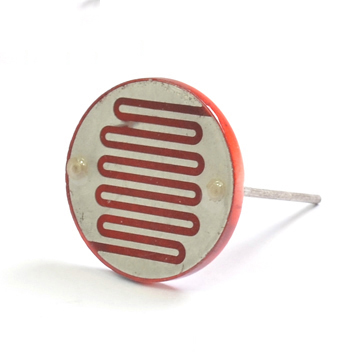
A photoresistor, or light-dependent resistor (LDR), or photocell is a resistor whose resistance will decrease when incident light intensity increase; in other words, it exhibits photoconductivity.
A photoresistor is made of a high resistance semiconductor. If light falling on the device is of high enough frequency, photons absorbed by the semiconductor give bound electrons enough energy to jump into the conduction band. The resulting free electron (and its hole partner) conduct electricity, thereby lowering resistance. 
About the light sensor module
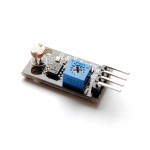
If you want to make a light controlled switch, a single photoresistor might be useless since you will need the digital signal according to the brightness. This module is designed for that purpose.

- using a high quality photoresistor
- working voltage: 3.3~5V
- output: digital switching (LOW or HIGH voltage on D pin) and analog signal (voltage output on A pin)
- using a wide voltage LM393 comparator that has good waveform
- output current >= 15mA, can directly light LED.
- with adjustable potentiometer to adjust the sensitivity
- has two M2.5 mounting holes
This module is very sensitive to ambient light, and is very suitable for detecting brightness of ambient light. The output signal can trigger Raspberry Pi, microcontroller like Arduino, or other digital relay modules.
When the ambient light intensity is lower than the predefined threshold, the output signal is high. When the light intensity reaches or exceeds the threshold, the signal output is low.
Connect the module to the Raspberry Pi
This light sensor module has 4 wires: VCC, GND, DIGITAL, ANALOG. The DIGITAL pin is the digital output while the ANALOG pin is the analog output. We can only use digital output directly on Raspberry Pi, because Raspberry Pi doesn’t come with any analog input pin.
You can use Dupont wires to connect it to the GPIO pins on Raspberry Pi.
Raspberry Pi Light Sensor Module
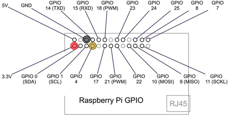
3.3v P1 —————————– VCC (V)
GND P6 —————————- GND (G)
GPIO4 P7 —————————– DIGITAL (D)


Example Source Code
Below is an example written in Python:
import RPi.GPIO as GPIO
GPIO.setmode(GPIO.BCM)
GPIO.setup(4,GPIO.IN)
for i in range(0,5):
    print GPIO.input(4)
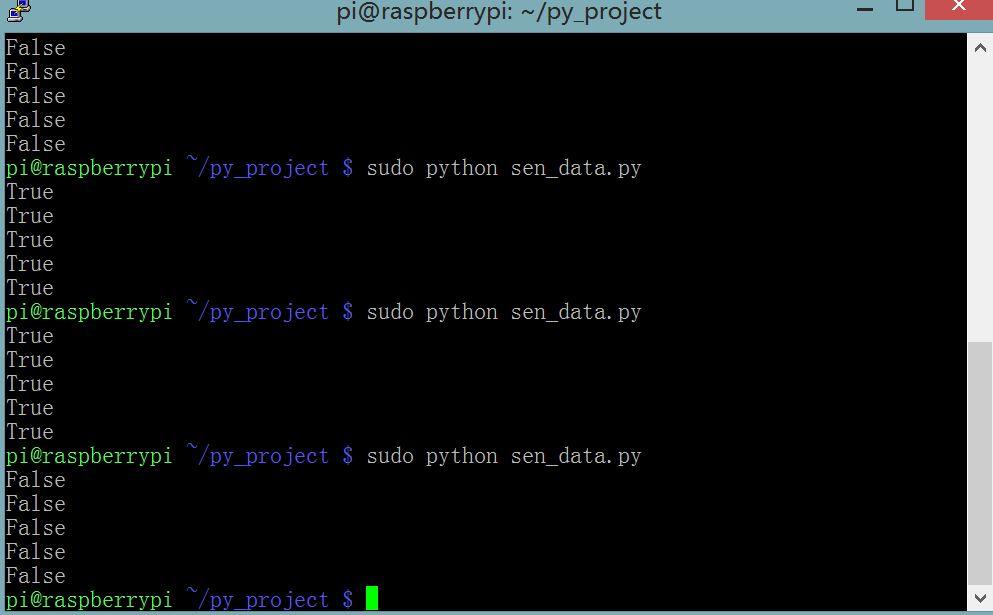
If you are in a bright room, using a bowl to cover the module can create a dark environment for it. If you are in a dark place, using a flashlight can trigger the flip as well. You can run the application and see the result change when lighting environment is changed.

