Description
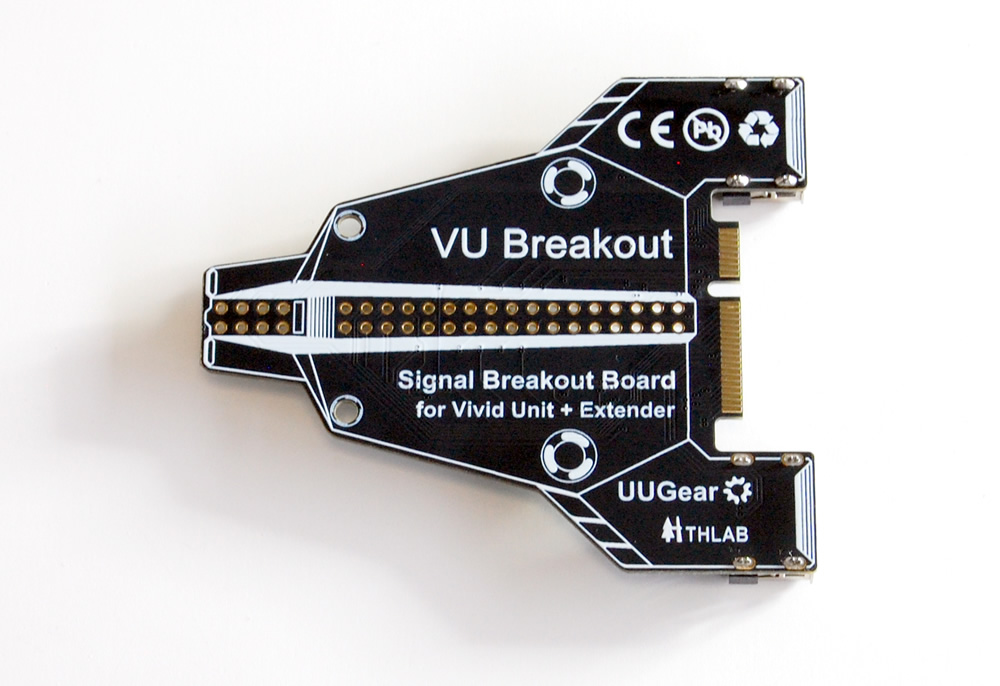
The VU Breakout is a compact yet versatile expansion board designed as an example of what’s possible when developing add-ons for the Vivid Unit Extender. Shaped like a small airplane, it combines playful design with practical functionality, making it ideal for demonstration, experimentation, further expansion, and integration with other systems.
VU Breakout is released as an example of expansion through the Vivid Unit Extender, as suggested by the Vivid Unit Expansions Specification.
VU Breakout is open-sourced. The software source code can be found in its GitHub repository. The schematic will be released on Vivid Unit’s website.
Key Features
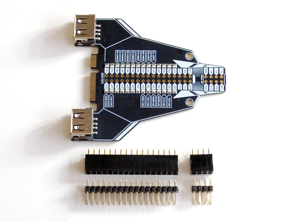
- USB Expansion: The VU Breakout routes two USB 2.0 ports from the Vivid Unit’s 4-pin headers to standard USB Type-A connectors, providing easy access to these USB interfaces.
- Comprehensive GPIO Access: All 28 GPIO pins from the Vivid Unit are broken out to a 2×17 pin header pad (2.54mm pitch), along with additional 3.3V signals, including Power Key, Extra Power Key, VOL+, and VOL-. This setup offers developers a full range of input/output options, supporting flexible prototyping and custom development.
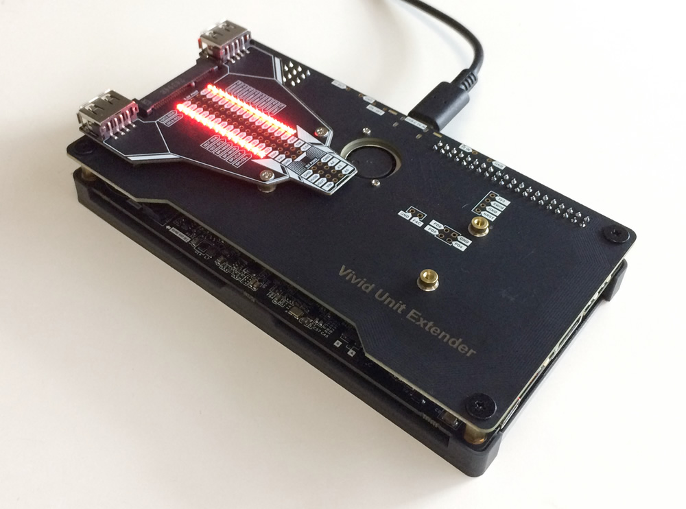
- LED Indicators for GPIO: Each of the 28 GPIO pins has a dedicated LED indicator that lights up when the pin is at a low voltage level, providing a quick visual reference for monitoring GPIO states.
- Additional 5V Signals: 5V-level signals, including ADC inputs (A0, A3, A4), VIN, and VUSB, are routed to a 2×4 pin header pad (2.54mm pitch), making these signals easily accessible for various applications.
- Included Connectors: The kit comes with 2×17 and 2×4 male and female headers (unassembled), allowing users to customize their connectivity based on project needs.
Technical Specifications
- USB Ports: 2 x USB 2.0 Type-A connectors, routed from the Vivid Unit via 4-pin headers
- GPIO Access: 28 GPIO pins routed to a 2×17 pin header pad
- 3.3V Signal Pins: Power Key, Extra Power Key (on Vivid Unit Extender), VOL+, VOL-, available on the 2×17 pin header pad
- 5V Signal Pins: ADC inputs (A0, A3, A4), VIN, VUSB, routed to a 2×4 pin header pad
- LED Indicators: 1 LED per GPIO pin, lights up when the pin is at a low voltage level
- Included Connectors: 2×17 and 2×4 pin male and female headers (unassembled)
Package Content
- Assembled VU Breakout PCB x 1 (headers are soldered)
- 2.54mm pitch 2×17 female pin header x 1
- 2.54mm pitch 2×17 male pin header x 1
- 2.54mm pitch 2×4 female pin header x 1
- 2.54mm pitch 2×4 male pin header x 1
Applications
The VU Breakout is designed for a wide range of applications, making it an essential tool for:
- Demonstrations: Illustrate the functionality and layout of the Vivid Unit’s GPIO and power signals with visual feedback from the onboard LEDs.
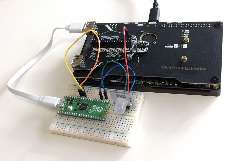
- Experimentation: Test and validate custom applications or circuits before moving to a final design.
- Further Expansion: Use the breakout to add components or modules that interface directly with the Vivid Unit’s GPIO, USB, and power signals.
- System Integration: Incorporate the Vivid Unit’s GPIO and power features into larger systems for seamless integration with external devices.
With its unique design, the VU Breakout provides an accessible and practical entry point into the world of Vivid Unit expansions. Whether you’re building custom extensions, prototyping a new idea, or demonstrating the capabilities of the Vivid Unit, the VU Breakout is a reliable and adaptable addition to your development toolkit.
Getting Started
- Soldering Headers: If you plan to use the headers, solder the provided connectors onto the board as needed.
- Connection: Before turning on your Vivid Unit, connect the VU Breakout to the Vivid Unit Extender via the Mini PCIe slot, and secure it with the M2 screws included in the Vivid Unit Extender package.
- USB Device Connection: You may connect USB devices to the two USB 2.0 ports on the breakout board.
The VU Breakout requires no software to function. However, you can use the default “vgp” software installed on the system to control the GPIO pins.
We’ve also developed a dedicated demonstration application for the VU Breakout board, called “vub.” To install it, run the following commands:
sudo apt update
sudo apt install vub
Once installed, you’ll find the “VU Breakout Demo” under the “Game” category in the application menu, or you can start it directly from the command line by typing “vub”.
The video below shows how this vub application works. After the simulated scene is ended, it continues working as a 2-band realtime audio spectrum visualizer, utilizing the built-in microphone on Vivid Unit.
Reviews
There are no reviews yet.